
September 2012 - Construction Phase 2
Assembling the crank case
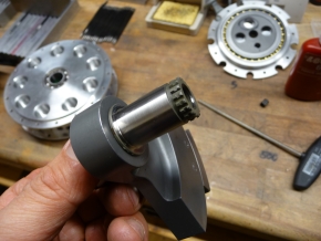
Newly made crank pins with splines to lock the head connecting rod.
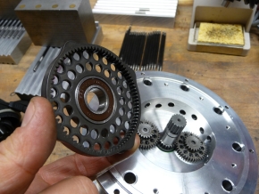
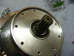
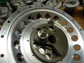
Assembling the cam disc into the center case with two gear wheels in between.
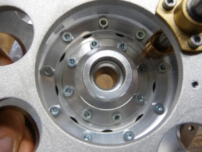
Assembling the clutch plate into the center case.

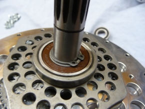
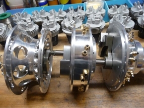
Assembling the crank shaft into the front panel
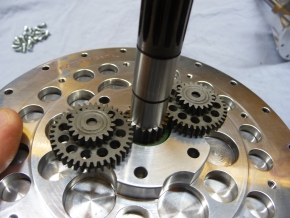
… and here two gear wheels are installed, too.
Assembling the cam disc in front
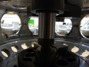
… good to see here: The crankshaft with running gears for the gear head.
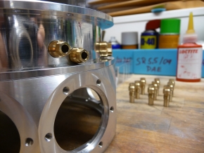
Installing the push rod guide into center case.
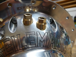
Installing the push rod guide into the rear plate of the cam disc lid with inclusion for the starter.
Rear plate with inclusion for the starter and compensation crank shaft.
Assembling the engine mount with inclusion for starter shaft.
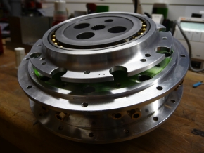
Rear plate with engine mount and starter inclusion, then central case with cam disc and clutch disc as well as front plate with cam disc lid (left to right).
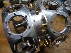
Left and right crank case with center case.
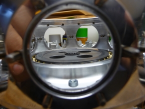
Inside view of crank case with clutch disc and support bearings.
Inside view of back crankshaft linked with starter compensation crank shaft and pinion.

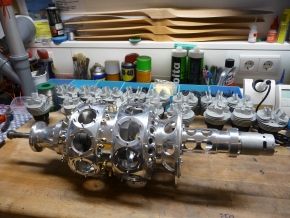
Pre-assembled 18-cylinder crankcase.
Complete assembly
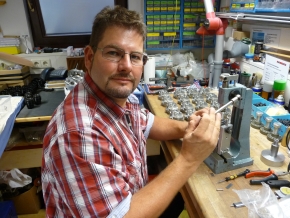
Andreas pressing in the sockets on the rocker arm shafts. What a lot of work!
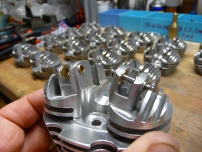
Cylinder head with sockets that have been pressed in and shafts.
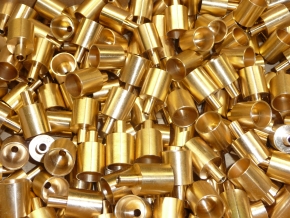
Valve cups for 18 cylinder heads. What a huge amount ...
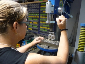
Elke drilling the valve cups ...
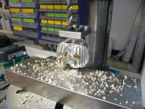
... with specially custom-made devices.
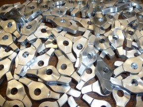
Many rocker arms, those need to be deburred and drilled.
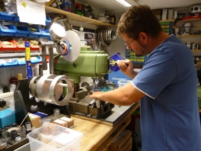
Andreas cutting rocker arm M3’s threads in high-strength aluminum – not so easy.
The time needed to build the device is quite astounding and should not be underestimated.
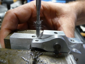
Cutting the rocker arm’s thread with a thread drill.
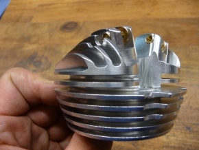
Our cylinder heads’ new form. It took two years from planning till production.
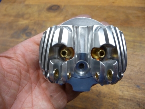
Very nice to see here: cylinder head with shrunk valve cups.
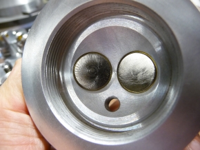
Hemispherical design of combustion chamber with valves built within.