October 2012 - Construction Phase 4
Piston, connecting rods, rings and bolts
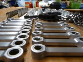
All connecting rods with in-pressed needle bearing are prepared for the next step.
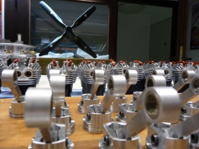
Also the pistons are deburred, washed, measured and ready for the installation.
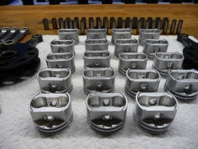
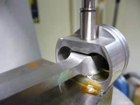
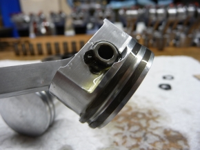
Assembling the connecting rods into the pistons with hardened and ground pins.
Before assembly, the needle bearings are washed in a special thinner and then soaked in oil.
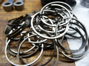
Mounting the 36 piston rings into the laid out pistons with mounted connecting rods. The installation is also done with oil.
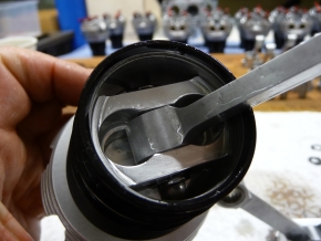
Fitting the pistons into the sockets, also with oil.
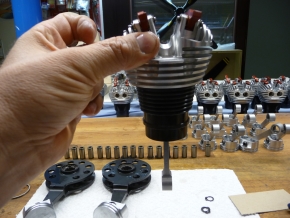
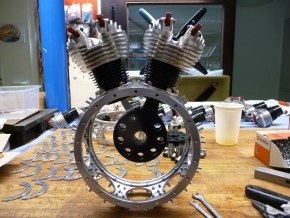
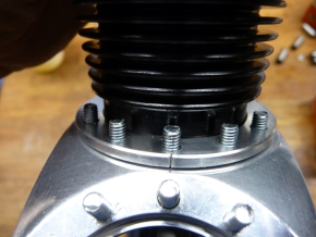
Assembling the individual cylinders into the engine cases that are already provided with studs.
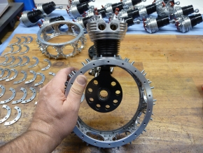
The connecting rods are mounted into the mother connecting rod. also with oil.
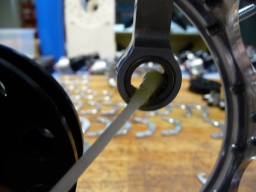
Mounting the connecting rod bolts into the mother connecting rod.
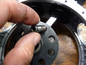
The connecting rod bolts are secured with circlips.
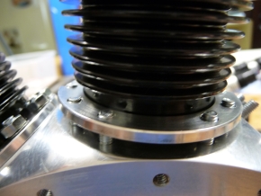
The cylinders are fastened onto the engine case with two-piece hold-down clamps.
Hold-down WITHOUT gaps (good to see here). We separate asymmetrically and use only one half.
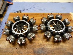
It’s getting there ...
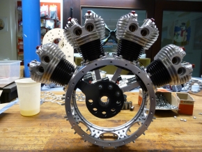
... and here are both finished engine cases with all 18 cylinders ready for the further assembly.